Last Updated on February 12, 2025
 Using a multimeter for the direct ignition system is much more effective, and this has diverse operating potential. If the ignition system malfunctions, always use a digital multimeter to test the four-pin ignition coil. Though there are various tools, the multimeter is the best because it is the most reliable.
What is the four-pin ignition coil?
The four-pin ignition coil needs a common type of system that stays within older cars. Some of the multiple coils are mounted on a single unit as the packing is ensured for each coil. There is a current feature that one may spark plug into the irreverent mechanism. The distributor’s ignition system may cope with the wasted spark system.
The distributor itself coins ignition timing as well as is controlled by the ignition control unit. One coil terminal firing within the batch of a resistant ICU fort. The compression stroke unless it goes into a chamber with its cylinder abstraction. The other terminal wastes completely inside the exhaust stroke of another cylinder. The coil pack works like the typical ignition coil.
What are the core parts of the four-pin ignition coil?
The four-pin ignition system contains four different circuits. Some of these inputs may be absent. Also, the ignition system may spark. Let us have in-depth writing about the circuits,
- The significant difference between the four-pin ignition coil is the vigorous Ground circuit that has nothing to do with the main proceedings. No ignition control module gets so interruptible, and the open circuit works in a typical ignition coil. Ground circuit with a core deceptiveness works well with the full-time conventional distribution system.
- The ignition coils rely on the two-wire connector within the Coil-On-Plug ignition chamber. The ignition module has an integration into the ECM. These severe regulations may have ascertained this Ground circuit. The ignition coil includes some of the ignition module operations merging with a cable system.
- The full-time ground correlates with the transistor. The Power Circuit has one of the coil-on-plug wirings. The supplying coils invade within a 12 volts sequence. The Coil-On-Plug ignition coils closely connect with the fuse or relay box.
- This system always consists of more than two input windings. There is a single output winding way for receiving 12 volts from the battery. The input windings are rocked with a reverse output winding. The output winding could be sparking all plugins to ignite the mainstream engine.
- The engine misfiring could be the most agonizing, and this may cause certain discomforts. There could be rough idling or failure to start. These symptoms may work well with the pack. There is a component that works pretty well. Performing tests on the coil package might diagnose the real issue quite well.
- Triggering Signal Circuit is one of the most crucial things to have a core mounting. One of the great characteristics of the four-pin ignition system is that it gets Triggering signals and also wakes up within the Switching signals. The triggering signal instructs the core transistor formula that is exactly causing the ignition coil to boil.
How does the four-pin ignition coil work?
The four-pin ignition coil is invented to act as a great power source and transformer section. This is responsible for eliminating high voltage that accelerates a huge amount of sparking modules. The engine has been initiated as the engine ECU discriminates all the aggressive signal dimensions. The ignition timing soars up the battery settings, and this emolument current flows through the IC section. Submerging the instruments into the primary coil might seem unpredictable, but it forms strong magnetic lines of force this time.
The IC is always interrupted by the current reduction of the flux. There is an electromotive force that directs the flux with an adjustment. This counteracts the secondary coil that emanates an electromotive force. The transmission of the spark plug shows about 30KV reading.
The turnover of the secondary coil seems more vibrant than that of the primary coil. The electromotive force compensates for the secondary coil. It seems very large compared to the current in the primary coil. The voltage interacts with the secondary ignition coil, hampering more definitive outcomes. Thus the four-pin ignition coil works very smoothly without any faults.
What are the Bad Ignition Coil Symptoms?
The 4-pin ignition coil works pretty well if it does not get attached to any bad wirings and connections. We can tell if the 4-pin ignition coil gets damaged if there is some mismanagement in the system.
A damaged ignition coil prevents the engine from getting started. It has been a primary reason for the main engine’s poor turbulence. Here are some of the points that need to be noted for realizing bad ignition coil symptoms.
- Power Reduction has become one of the most prominent issues and needs proper identification to resist this acute sense. The core intention has so many similarities with the adjacent system. A bad ignition coil makes the car operate in a traditional manner.
- It invents a wide range of idling time. By the end of the process, it may fluctuate some power. The sound system may feel rough. This might stall quite badly, and in the end, it accelerates pretty slowly. The Engine Light will come to daylight if there is nothing to do with the annual demonstration.
- The faulty ignition coil could have been imposing a different code. If you see some engine misfiring, surely there is a perfect cause behind this. The Deterioration of Gas Mileage seems a more vulnerable issue.
- A slashed gas mileage collaborates with the solid sign, which has been provocative due to some extent. If you see a car facing difficulty starting itself, you should be super sensitive about the issue.
- If the spark plug causes bad collateral damage, then you need to have a proper system building down enough power sources. If the receiving channel initiates the spark plug, you’ll have difficulty starting your car.
- Suddenly Backfiring is another massive issue that is so depressing. A sputtering sensation is the greatest threat to the engine. This makes a great impact on regular speeds.
- It seems some kind of unburned fuel escapes without the exhaust fuel’s permission.
- This erroneous ignition coil makes the engine run rough. There is a bad vibration when the car is not running.
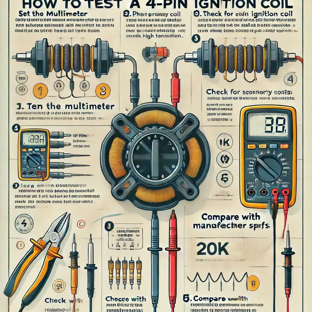
The process of testing a 4-pin coil pack with the Multimeter
You can test the four-pin coil pack in your own method. But if you need any practical guidance, then I bet this is going to be the most simple illustration of the procedure of testing four pack coil pack with the Multimeter,
In the very first stage, you need to have a quick run-through of the four-pack coil ignition system and then initiate the process of how to diagnose a coil pack. The primary resistance of the 4-pack coil ignition makes it decent as the main arousing factor. Let us dive deeper into each of the stages. While the testing procedure shows how to test secondary resistance, we will try to discuss that in a completely new way.
STAGE-1: Understanding the location of the coil pack
In the very maiden stage, the main thing to be done is to have a proper idea of the Coil Pack Location. We must discuss the ignition coil pack modulation system when the car engine is powered off. In order to find that within your engine, first take a normalized step to figure out what is going on inside the chamber; you may see through a take-off to perform the run tests. The engine manual is the easiest way to habituate the spotting mechanics. It would be best if you found out where the pack is located, and keeping it aside could make you feel so much more tempered, to begin with impression technology.
STAGE-2: Test the sparking plug
The spark plug has been detected on the top of the primary engine. The fluctuation of the wiring readings is normal in the coil pack. The location of the back of the engine remains idle as well as this denotes the greatest middle efforts of them all. Test The Coil Pack, and for that, remove the internal congestion cover. Detach the sparking plug as well as the sizzling wirings. The robust wirings from the coil terminals insist that with a selective figure. You need to take the unit at daylight to make a bit out of the multiple coils.
STAGE-3: Check all the electrical connections
Remember that some of the coil packs are disconnecting spark plug wirings. The output tower terminal disguises coils on the pack. After disconnecting the wirings, adjust the label so that this makes it simple to identify and map. Again reconnecting them will restabilize the matters.
At the end of the process, dismiss the pack’s electrical connection as well as make a good piece of the wide connector and then attach them to the main pack body. Introduce a wrench or plier to have a hard move to the ratchet and socket. When it is out then, make sure that the Multimeter is Set To the perfect range.
STAGE-4: Perform a preliminary meter setting
Calculate the resistance of the primary fusion input that has collaborated with the windings of each coil. Set the Multimeter to the predetermined range, and have a decent omega symbol on the meter. Place Multimeter Probes to the redirected First Terminal. The input terminals should look like incremental bolts. The identical tabs need to be identified as bolt threads. It would be best if you connected them with the primary meter windings. Within the coil is a perfect pack, and four terminals are within it. Make this placement quite effective and build the most promising chamber of lightning.
STAGE-5: Examine the respective probes
Check the multimeter to see if it is of decent quality. Make the incentive meter Reading flawless once the Multimeter connects properly with the terminals. A decent ignition coil may have presented a core value between meter readings. The engine specifications are the core determiner of what bears the right resistance.
A metal part of the output tower consists of multimeter probes. Place another probe and also feel the rest of the action. The input terminals could move forward and contact the resistance value. It presents the core multimeter devaluation, as well a good ignition coil must not exceed the present value. A general value of the wirings could not be much more than an outpost multimeter value. The readings between 5,000 Ohms to 12,000 Ohms are considered standard values. If the terminal values are between 5.0 and 12.0, then the meter should have been decent, like the confined value.
STAGE-6: Inject the primary coil terminals
Set the Multimeter to the perfect ohm range and then measure the ignition coil’s last but most efficient secondary resistance. The ohms setting must include the Omega meter devaluation. Place The Probes On the primary Coil Terminals as well as these make a strong, and The output terminal produces a severe tower mechanism. The single connection immobilizes the ignition coil’s secondary winding database more agonizingly. A value must be given at the mean range. The coil seems so much worse on the way it needs to replace the entire scenario.
STAGE-7: Perform a resistance testing
Suppose there is a short circuit happening within the coil junction. It would help if you protectively replaced the whole fuse box. If that does not make any sense, then keep the idea within the banking channel. Move to steps for keeping the whole transaction into a junction as well as the system, has a big and bad movement of the secondary resistance. All these terminals make the most of it as soon as it is sparking plug wirings. After that, the assistant turns the key to the activated position. Testing each of the input terminals seems pretty much shaky.
STAGE-8: Compare the measured and standard value
The appropriate value depends on the actual specifications of the 4-pin coil. There is a core impact of the ignition coil model. If the black and red probes are connected decently and consist of the appropriate range, then you will get the standard value of the four-pin coil. That means that the coil is in perfect condition. By following the method, move to other coils one by one. If the readings do not match the real value, you must replace the entire coil pack. That’s how you can check a 4-pin coil pack with the help of a multimeter.
Final Verdict
You may face a louder engine because the 4-pin ignition coil pack may not have functioned in a proper way. What could be the greatest way rather than testing that with the help of a digital multimeter? Lack of power and slashed RPMs are signs of a worn-out coil pack. If the value is dropped, somehow test the vehicle’s coil pack as soon as possible.
Calculate the resistance of the primary and secondary terminals to determine the real issue. A malfunctioning 4-pack ignition coil pack could be so threatening to the system. So to have the right resistance, you need to have better collaboration between the functions. These facts have a great impact on engine performance. Remove each coil gradually to detect the original issue. We hope that you will be benefitted enough by following these guidelines. Properly follow this to have the best multimeter output ever.