Last Updated on August 20, 2021
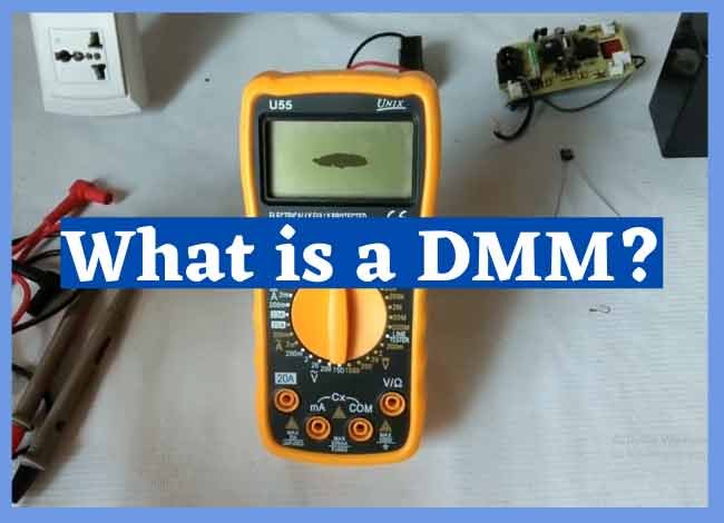
A Multimeter is a vital tool that is used by electricians and engineers to measure electricity. Unlike other tools, a multimeter can be used to perform various tasks such as measuring current, resistance, voltage, frequency, capacitance, continuity, and temperature. A professional electrician will always select a quality multimeter with useful features.
My question is; do you know how to use a multimeter? With so many types of multimeters on the market, there are some that are easy to interpret and use, while others need expert knowledge. But still, there are common features that almost every multimeter comes with. We’ve come up with this article to help you know the different parts and how to use a multimeter by testing the main three things in electricity, which are voltage, ohmmeter, and ammeter.
Step one: Understand the multimeter and its parts
- Identify the dial meter – this is usually arc-shaped with scales visible via the window and pointer, which will clearly show the values read from the scale. The marks on the meter dial face may be of varying colors that show every scale. Thus they might have different colors. Actually, these define the ranges of the magnitude.
- Identify the knob or selector switch – this is the part of the meter that enables you to change the function between ohms, volts, and amps and to change the scale of the meter. A lot of functions have different ranges, so it’s crucial to have both sets correctly, or there might be severe harm to the meter or the operator.
- Identify the ports for inserting the test leads – the usual ports to find on a multimeter are “COM” or (-), which stands for common. This is the port where the black test lead is connected. The other port is indicated as “V” (+) and the Omega symbol for Volts and Ohms, respectively. The + and – symbols stand for the polarity of probes when set for testing dc volts. You can learn more about multimeter symbols here.
- Identify the test leads – normally, there are two test leads or probes. One is in black color while the second one is in red. These are utilized to connect to the gadget that you’re planning on measuring or testing.
- Check out the battery and fuse compartment – normally, this is based at the back of the meters. But some models have them on the sideways. The compartment holds the battery that supplies the power to the meter for resistance tests.
- Identify the zero adjustment knob – it is normally located close to the dial labeled “ohms adjust” or “O Adj’. It is applied in the ohms or resistance range, while the probes are shorted together.
Step two: How to measure Voltage (Volts)
- Begin by setting the meter for the highest range given for ac volts
Most of the time, the voltage to be measured has a value that is unknown. Hence, the highest range possible is chosen so that the meter circuitry and movement will not be harmed by a voltage greater than expected.
- Put in your test leads
The second thing to do is to place the black test lead in the “COM” or – port and the red test lead in the “V” or + port.
- Identify the voltage scales
There might be various volt scales with different maximum values. The range selected by the knob defines which voltage scale to read. As a matter of fact, the maximum value scale should coincide with selector knob ranges. Such a scale is accurate anywhere along its length.
- Test a common electrical outlet
It depends on your location as some outlets have volts of 120 to 240 like the USA, while other places have 240 or 80 volts. Place both the black and red test leads into the outlet; it should grip it as it does with the plugs. A voltage of near 120 or 240 should be indicated.
- Disengage the test leads
Then, rotate the selector knob to the lowest range given, which is greater than the voltage shown (120 or 240), in the case of the USA.
- Reinsert the test leads
Place back the test leads, and the meter might show between 110 or 125 volts this time around. The range of the meter is vital to get precise measurements. The correct mode should be set, and failure to do that may lead to the pointer not moving. Also, you can attempt both modes if the pointer isn’t moving.
- Avoid holding both the test leads
When making tests. Try as much as possible not to connect and hold the two test leads at ago. This may lead to burns or even injury.
Step three: How to measure Resistance (Ohmmeter)
- Set the meter to resistance or ohms
Switch the multimeter on. If the meter measures resistance in ohms, it can’t measure continuity because resistance and continuity are reverses. When there is small resistance, there will be great continuity and vice versa.
- Check the meter indication
When the test leads are not in contact with anything, the pointer of an analog meter will remain at the left position. This shows an infinite amount of resistance. Also, it is right to say there is no continuity.
- Connect the test leads
Connect the test leads with the black one in the “COM” port and the red one in Omega or “R” port.
- Hold the probes at the end of the test leads
The meter pointer should move to the right side. Identify the “Zero Adjust” knob and rotate it so that the meter shows “0” or close to zero.
- Measure the resistance of an item like a bulb that is good. This will move the pointer from resting at the left and move fast to 0 on the right side.
- Attempt various ranges
Change the range of the meter to R X 1. Zero the meter once more for this range and repeat the process above. Inspect how the meter did not move as far to the right as before. The scale of resistance has been changed so that every number on the R scale can be read directly.
- Test resistance between hands
Set the meter to the greatest R X value possible and zero the meter. Loosely hold a test lead in both hands and read the meter. Verify the resistance is reduced.
- Ensure that your reading is correct
It is really vital that the test leads do not get in contact with any other device rather than one being tested.
Step four: How to measure Current (ammeter)
- Ensure that you’ve measured the voltage first
First of all, you’ve to know if the circuit is ac/dc by measuring voltage first which you’ve read about above.
- Set the meter to the highest ac/dc amp range supported
The meter is needed to measure the same mode, which can be ac/dc amps as the voltage in the circuit. So, if the circuit is dc and the meter only measures ac, then you should not proceed.
- Consider utilizing a “clamp-on” ammeter
It is great for home use. It was created to measure the current through a 4700-ohm resistor across 9 Volts DC. Perform the test by placing the black lead in the “COM” port and the red one in the “+” port. Then, shut off the power to the circuit. Open the part of the circuit that is to be tested. Place the meter in series with the circuit in a way that it completes the circuit. Check the polarity. Current moves from positive to negative and sets the range of the current to the greatest level. Put on power and adjust the range of the meter downward to enable accurate reading of the pointer on the dial.
- Be keen on any filter capacitors or other elements that need surge current when switched on
To avoid this from occurring, constantly utilize the higher range measurement protected by, the higher fuse rating and be very careful.
If you’ve been finding a multimeter to be difficult to use, you can now follow our steps above to properly take tests and measurements on your electrical appliances.


