Last Updated on December 9, 2022
Are you new to multimeters and want to find out how they work and how you can use them? Then, you have just landed on the right page.
A multimeter is an indispensable tool that every electrician, mechanic, or DIY enthusiast should’ve on them always. Multimeters are used for different purposes. This device will help you to diagnose circuits, test batteries, check power in appliances, etc. The basic function of a multimeter is to measure voltage, current, and resistance. But some other advanced digital multimeters can measure other things like capacitance, temperature, diodes, and frequency.

In Simple: What is a multimeter?
A multimeter is a device created to measure electrical and electronic circuits. But unlike many other tools, an HVAC multimeter is very convenient in that it measures different things just in one tool. You can measure things like voltage, current, resistance, continuity, capacitance, temperature, diodes, and frequency.
Types of Multimeter
Typically, there are two types of multimeters. They are digital multimeters, which are also referred to as “DMM” and analog multimeters. Analog multimeters were the first to be discovered before introducing digital multimeters. An analog multimeter uses a moving pointer to carry out its measurements, while a digital multimeter displays figure digitally. The analog pointer points out the voltage and things being measured. Digital multimeters are the easiest to use and have become very common among electricians and mechanics.
In some cases, like measuring electric currents that change very fast, analog multimeters are preferred over digital multimeters.
What type of multimeter should I buy?
Multimeters have undergone a lot of changes. So, I suggest you pick a digital multimeter over an Oscilloscope multimeter. Because digital multimeters are very easy to use and can perform a wide range of functions when compared to an analog or Oscilloscope multimeter. Unless you have some special functions like measuring electrical currents that change very fast, a DMM is the best.
Why do you need a multimeter?
You need a multimeter for various functions such as checking your car battery, knowing if the wire is hot or not, and knowing what is happening in your circuits. Every time something in your circuit isn’t functioning, the multimeter can help you troubleshoot it. Some of the electronic projects that will need a multimeter include knowing how much current is flowing through an LED, knowing if the switch is on, checking how much power you have on the car battery, and also finding out if the wire is conducting electricity or if it is broken.
So, having a multimeter as you carry out electrical repairs on an appliance, house, or car is very vital. It will prevent you from assuming things and know if there is a current in the circuit you are dealing with or if there isn’t.
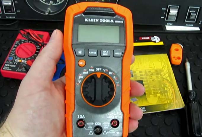
Parts of a multimeter
If you are not familiar with multimeters and want to start using them, it is a great idea to familiarize yourself with them first. It doesn’t matter if it’s an analog multimeter or a digital multimeter. You have to know where to place the ports and which settings to adjust. Also, you have to know what the different signs on the multimeter mean and how to use them.
Usually, a multimeter is made up of 4 sections. These are the display area, selection knob, ports, and probes. The display screen is where the measurements are shown. Analog multimeters have a display that is a bit challenging to read, and determining the exact result can be challenging. So, you need to learn What do the Symbols on a multimeter mean, and that’s why you usually utilize them by experts and not beginners usually utilize them. On the other hand, a DMM comes with a digital display screen that clearly shows the results in figures. Therefore, it is very easy to read, and even beginners can interpret it. Some advanced DMMs have a lit display that allows the reading of results even in dark or dim places.
The other sections on the multimeter are the selection knob which is used to select what you want to measure, the ports are the areas or holes on the multimeter where you plug the probes, and finally, the probes are the two red and black wires that are inserted in the device and to the equipment that is to be measured. Know that there is no difference between the black and red probes. But also, ensure that the black probe is always plugged in the COM port, while the red probe can be placed in one of the other ports depending on what is being measured.
How does a multimeter work?
So what is a DMM, and how does it work? The operation of a DMM is comparatively straightforward, even though there are some apparent differences in how digital multimeters from different manufacturers work. The major process that happens within a digital multimeter for any measurement that occurs is that of voltage measurement. Every other measurement is derived from this basic measurement.
To understand the DMM better, you need to know about the ammeter, ohmmeter, and voltmeter. Ammeter measures current, the voltmeter measures voltage, and an ohmmeter tests resistance. A multimeter combines all these three functions in just a single device.
Related article: Which is Better Between Ohm Meter and Digital Multimeters for Electronics Work?
The function of the ammeter is to measure the number of electrons passing a particular point for a certain period of time. And the units in this measurement are known as amperes. On the other hand, the voltmeter is used to measure the electrical potential between two points in volts. Finally, the ohmmeter is used to measure electrical resistance, which is opposite to the current. Ohmmeter uses ohms as its unit. For instance, an electrical circuit can be said to have a resistance of zero or near zero ohms if it’s short-circuited. But when the circuit is open, then it has infinite resistance and no current flow.
What are AC and DC current?
Another great feature of the multimeter is that they allow you to measure voltage and current in two different modes, which are AC (alternating current) and DC (direct current). Direct current is that current that always flows in one direction, while Alternating current is that current that changes direction, normally several times in just one second. For instance, direct current is supplied by common batteries such as AA and AAA batteries or the battery of your phone. Also, different multimeters have different symbols for DC and are usually abbreviated as follows: “DCV” and “DCA,” or “A” and “V.”
Alternating current or AC standards differ from one country to another. So, you shouldn’t assume that if an electrical appliance functions in the UK, it will still function in the USA without any problem. Don’t assume, but measure the voltage before switching on the appliance. AC is also common in household outlets, while DC is supplied in batteries. You should also avoid using a multimeter to measure wall outlets in your home as it can cause havoc. Some of the AC symbols used by different manufacturers include “ACV” and “ACA” or “A” and “V.”
How to use a multimeter?
First, you have to learn how to read a multimeter reading. A basic multimeter is used to measure voltage, current, and resistance. But an advanced device will measure more than this. Actually, this is where the name “multi” meter is derived from. Depending on the type and advancement of the multimeter, you can use your device and measure one of the following:
Measure voltage
You can either measure AC voltage or DC voltage. The “V” with the wavy line means AC voltage, while the “V” with a straight line means DC voltage.
- Switch off the circuitry or wiring under test if there is a danger of shorting out tightly spaced adjacent wires, terminals, or other points which have varying voltages.
- Insert the black probe lead into the COM socket on the meter
- Insert the red positive probe lead into the socket marked V or with the omega “Ω” symbol.
- If the DMM has a manual range setting dial, then adjust it to choose DC or AC volts and select a range to provide the much-needed accuracy. While if the meter is auto-ranging, adjust the dial to the “V” setting with the symbol for DC or AC.
- Ensure that you connect the multimeter in parallel to a circuit in order to measure voltage. Therefore, the two test probes should be connected in parallel with the voltage source, load, or any other two points across which voltage requires to be measured.
- Touch the black probe against the first point of the circuitry or wiring.
- Afterward, power up the device.
- Touch the second probe (red probe) against the second point of the test. When doing this, make sure that you don’t bridge the gap between the point being tested and adjacent terminals, wiring, or tracks on the PCB.
- Before measuring voltage, ensure that you set the range dial on the meter to AC volts and the highest voltage range.
- You can now take the reading on the LCD screen
Measure resistant
- Switch off all the power to the circuit being measured
- Plug off one end of the resistance from the circuit. It may involve pulling off spade leads or desoldering a part. This is very vital as there may be other resistances in parallel with the resistance being tested.
- The probes are connected to the meter in the same way as when you measure voltage.
- Afterward, adjust the dial to the lowest ohm or Ω range. This is very likely to be in the 200-ohm range.
- Put the probe tip at every end of the resistance being measured
- In case the display screen shows “I,” then this implies that the resistance is greater than it can be displayed in the range setting that you’ve selected. Hence, you must turn the dial to the next highest range. Do this several times until a value is shown on display.
Measure current
- Switch off the power in the circuit being measured.
- For a multimeter to measure current, you need to place it in a series with the load in a circuit. Simply insert the black probe into the COM socket and the red probe into the high current socket or the mA socket.
- After connecting the meter, adjust the dial on the meter to the highest current range or the 10A range if the probe is in the 10A socket. But for auto-ranging meters like Klein mm600, set the dial to mA or “A” setting.
- Switch on the power
- In case the range is extremely high, you can adjust to a lower range in order to get a more accurate reading.
- After you’re done measuring the current, you can return the positive probe or the red probe to the V socket. When the meter’s lead is in the mA or 10A socket, then it can be said to be a short circuit. And if you forget and connect the meter to a voltage source when the lead is still in this position, you may actually end up blowing a fuse or the meter.
Measure continuity
One of the importance of a multimeter is to check blown filaments in the bulbs and the blown fuse breaks in flexes of appliances and tracking paths on PCBs.
- Adjust the selecting dial on the DMM to the continuity range. This is usually shown by a symbol that looks like a series of arcs of a circle.
- The probe leads are linked to the meter in the same manner as when you measure the voltage.
- In case a conductor on a wire or circuit board in an appliance wants to be inspected, ensure that the device is switched on.
- Afterward, put the tip of a probe at every end of the conductor or fuse, which requires to be inspected.
- So, if the resistance is less than about 30 ohms, the meter will show this by beeping or making a buzzing sound. Additionally, the resistance is as well shown on the display screen. And if there is a break in continuity in the gadget being checked, then an overload indication, normally shown by the digit “1”, will be visible on the meter.
Related article: What are the feature differences between Clamp Meter and Multimeter?
Test Diodes
You can use a multimeter to know if a diode is open-circuited or short-circuited. Actually, a diode is an electronic one-way valve or check valve, which simply conducts in one direction. When a multimeter is connected to a working diode, it shows the voltage across the component.
- Start by adjusting the dial of the meter to the diode testing, which is shown by a triangle with a bar at the end.
- The probes should be connected to the meter in the same manner as for measuring the voltage.
- Touch the tip of the negative or black probe to one end of the diode and the tip of the positive or red probe to the second end.
- After the red probe makes contact with the anode and the black probe is in contact with the cathode of the diode, the diode conducts, and the meter shows the voltage.
- When the probes are placed either way, and the meter indicates “1”, then know that the diode and the open circuit are probably defective. While if the meter displays a value close to zero, just know the diode is short-circuited.
- If a component is in a circuit, resistance in parallel will affect the reading, and the meter may not show “1” but a value that is less.
Summary
A multimeter is a device that can let you know if your appliance has the needed power or not. Instead of guessing things, you should take this device and use it to test different components. It can be voltage, current, or even continuity.
In order to get accurate results, you need to select a high-quality and reliable multimeter like Fluke 87V or Fluke 289 True-RMS Logging multimeter. Consider picking a multimeter that offers accurate results, has a large display area with a backlit screen, then click or knob should be easy to use, and the probes should be decent. Brands such as Klein, Fluke, Mastech, Innova, and Amprobe, should be highly considered.